 |
||
 |
 |
 |
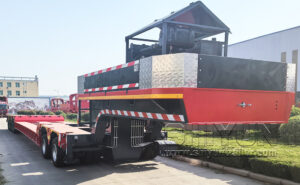
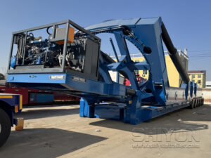
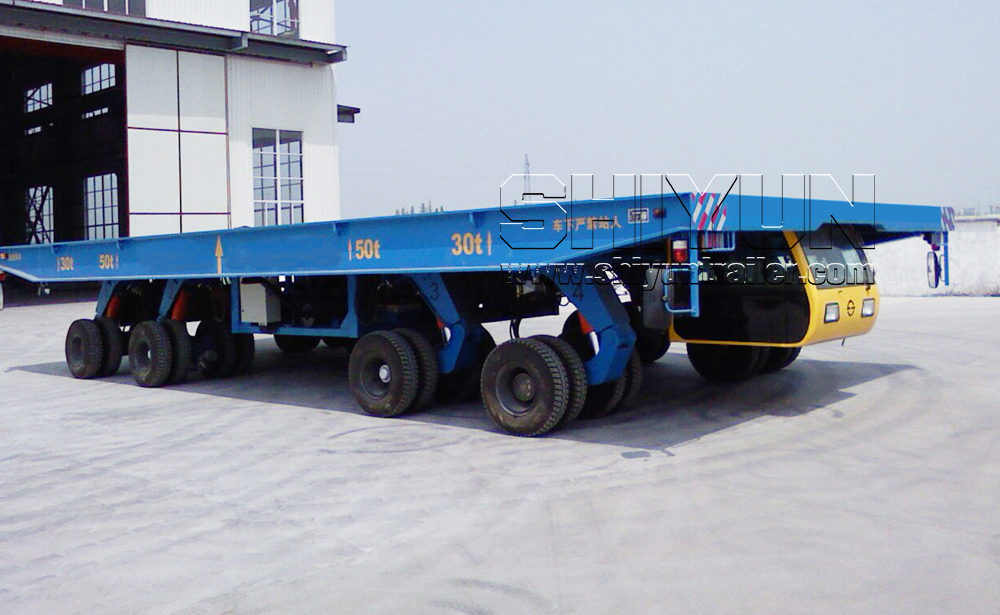
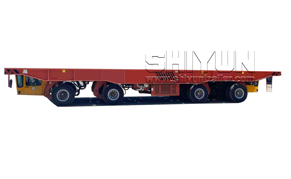
The core feature of the SHIYUN hydraulic flatbed transporter is hydraulic lifting and leveling. It can be operated via onboard cab or wireless remote control.
It is mainly used for in-plant transportation, widely applied in shipyards, marine industrial parks and heavy industrial zones.
It is commonly used for the handling and transfer of hull sections, complete hull blocks, bow and stern components, ship superstructures, large steel structures and hull modules inside workshops.
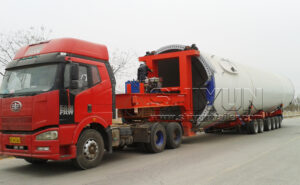
It is also suitable for the heavy-duty in-yard transportation of large pressure vessels, offshore engineering equipment and other heavy oversized cargo.
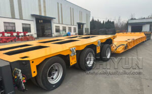
Designed for hull blocks / sections & dock transfer; 35–1000 ton capacity. High-strength one-piece frame, rigid & torsion-resistant for heavy ship components.
Ground-level travel for easy access to docks & ramps; large hydraulic lift stroke adapts to different dock blocks & heights for precise positioning.
4/6/8/16 axles optional; independent hydraulic suspension + auto-levelling. Stable transport, protects hull accuracy, mm-level positioning.
Electro-hydraulic servo steering; straight, diagonal, crab, 360° in-place rotation. Precise docking in narrow docks/berths.
Dual engines + dual-pump confluence hydraulic system. One engine fails, the other keeps running; supports 24/7 continuous transfer.
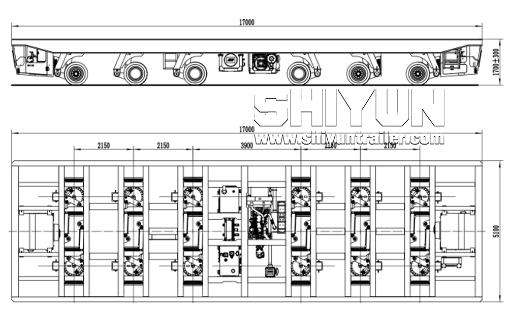
Standard long deck; dual telescopic beams optional, extendable to 12m. Ideal for long hull sections & superstructures.
Front/rear driving cab + wireless remote. Safe long-distance operation in docks & confined spaces.
Shot blasting + heavy-duty anti-corrosion paint; marine-grade electrical/hydraulic components. Long life in coastal high-salt environments.
Overview
This self-propelled, self-lifting tire-mounted flatbed transporter is custom-built to carry hull segments and other heavy structural parts, acting as a vital transport link connecting different working stations in modern shipbuilding workflows. Its complete assembly covers platform frame, drive suspensions, passive suspensions, power pack engine assembly, hydraulic lifting setup, hydraulic drive assembly, hydraulic steering assembly, hydraulic oil supply station, braking assembly, on-board electrical circuit and microelectronic control system.
The power assembly is installed under the vehicle frame, made up of a diesel engine, elastic couplings, variable displacement hydraulic pumps, hydraulic oil tank, fuel tank and supporting auxiliary fittings. Engine specifications are matched rationally based on rated load weight and onsite operating needs. Its power output can satisfy full-load hill climbing performance and support prolonged non-stop operation. An electric foot throttle system handles the engine’s throttle adjustment.
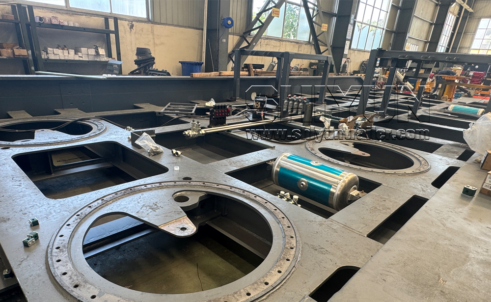
The frame is constructed from high-strength Q345 grade B steel, which delivers excellent bending resistance and reliable torsion flexibility. The overall strength and rigidity of the vehicle feature ample safety allowance to withstand evenly distributed cargo loads. Standard warning labels are mounted around key areas: “Warning: High Temperature Burn Hazard” beside the engine exhaust pipe, and “Warning: Pinch Point Risk” around the cabin door and window frames. Lifting lugs are welded onto the steel frame, with their installation positions clearly marked on the outer surface of longitudinal girders. All parts mounted beneath the frame (operator cabin, oil cooling tank, hydraulic oil tank, cooling water tank, electrical control cabinet, intercooler, diesel fuel tank) come with dedicated shock absorption buffers. Detachable grid steel plates form the load-bearing lifting platform, with a minimum actual thickness of 5 millimeters.
This flatbed transporter adopts a hydrostatic drive configuration to deliver steady acceleration and stable running. The foot pedal accelerator synchronously regulates diesel engine RPM and vehicle travel speed, offering stepless speed adjustment from 0 to 12 km/h to fully tap the engine’s power performance. A torque buffer connects the diesel engine and hydraulic pump. The variable displacement pump transfers power through closed hydraulic pipelines to variable hydraulic motors integrated within drive axles. These hydraulic motors output driving torque to planetary reduction gearboxes, pushing the vehicle to move under predefined travel modes.
Hydraulic Suspension
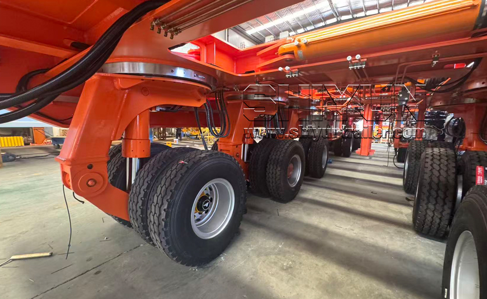
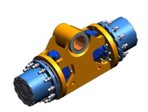
Hydraulic suspension is divided into drive suspension and brake suspension, mainly composed of suspension bracket, balance arm, suspension cylinder, drive axle, brake axle or follow‑up axle, wheel rim, tire and other components. The wheel axle enables the whole vehicle to have a vertical adjustment range of ±300 mm through the expansion and contraction of suspension cylinders. A reducer and motor are installed on the drive suspension to realize vehicle travelling function. The brake suspension is equipped with brake axles with brake air chambers to service service braking and parking braking of the vehicle.
Slewing Bearing
single‑row ball slewing bearing is adopted. Both the inner and outer races of the slewing bearing are forged from high‑quality alloy steel, delivering strong load‑bearing capacity. # 7. Tire Specification The tire specification of the flatbed vehicle is 8.25‑16.
Hydraulic Steering System
The flatbed vehicle adopts electronically controlled‑hydraulic steering to realize multi‑mode steering.
The wheel set is driven by a hydraulic motor directly mounted on it through a wheel‑side reducer, and can swing to adapt to cross‑slope conditions.
Brake Axle
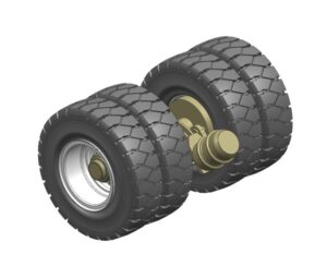
The flatbed vehicle adopts a pneumatic braking system. The equipment can be braked at any time as required during movement, with reliable braking performance.The vehicle is also equipped with a parking brake. When the vehicle is out of service for a long time, the hand brake valve and parking relay valve cut off the braking air of dual brake wheel cylinders, enabling the parking springs to clamp the wheel sets tightly.
The pneumatic braking system is supplied with air by the engine‑built air compressor. Air is cooled via heat‑dissipating pipes, then filtered and dehumidified by an air dryer. Afterwards, the air flows to a four‑circuit protection valve, which keeps the dual pipelines separated to prevent air backflow and leakage
Heat dissipation of hydraulic oil is implemented in two separate circuits. One hydraulic cooling system separately cools the return oil from the hydraulic drive system before returning it to the hydraulic oil tank. The other hydraulic cooling system draws hydraulic oil from the tank via a hydraulic pump and feeds it into the cooler for cooling, after which the cooled hydraulic oil flows directly back into the tank.
13.Cab
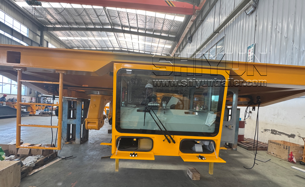
One control cabin is installed below each longitudinal end of the load‑bearing platform. Each cabin is equipped with a 360‑degree industrial‑grade camera and display monitor.
Every control cabin features good ventilation, windscreen wipers and cleaning devices. The seat is adjustable forward and backward with a reclinable backrest. Both cabins are fitted with independently temperature‑adjustable air‑conditioning units and fans with external units. Air‑conditioning outlets are reasonably arranged with concealed pipelines. The air conditioners are electrically powered (independently installed, not driven by diesel engines) and only available when the cabin enters the operating mode.
Cab doors are rear‑hinged, fitted with sliding glass panes. Door and window glass is safety glass, providing the operator with good forward and lateral visibility. Each cabin is equipped with a fire extinguisher, two rear‑view mirrors and sun visors. Control switches, equipment displays and gauges are rationally arranged to ensure easy operation and safe monitoring of the flatbed vehicle.
14.1 Hydraulic Pipe Burst‑proof Device
A dual‑line protection valve is adopted to protect the lifting system. In case of pipeline rupture, pressure drop will rapidly generate a flow pulse to seal the damaged pipeline at the explosion‑proof valve. The other pipeline keeps all cylinders of its group connected. The full‑axle load compensation function is completely maintained, enabling the transporter to continue its transportation tasks.
14.2 Overpressure Protection Device
Each circuit of the hydraulic lifting system of the flatbed vehicle is equipped with an independent overflow valve to prevent system overload and protect lifting cylinders and wheel frames.
14.3 Overload Prevention Device
Pressure sensors are installed at four corners of the lifting system to monitor platform load in real time. The buzzer inside the cab will sound in case of overload or eccentric load. The vehicle will be prohibited from travelling when the load at any single point exceeds 10% of the rated value.
14.4 Emergency Lowering Device
An emergency lowering safety valve is fitted under the frame platform for manual platform lowering under emergency conditions.
14.5 Emergency Stop Function
One emergency stop button is installed inside each cab and at four corners under the frame to stop the vehicle in emergencies.
14.6 Lighting and Warning Devices
Each side at both ends of the load‑bearing platform is equipped with rear‑view mirrors, normal work lights, turn signals, brake lights, running warning lights and buzzers. Perimeter light strips around the vehicle for night operation are also required. Four‑corner work lights with vertically adjustable illumination angles are provided. All lamps and buttons have an IP66 protection rating.
14.7 Lifting Platform Cover Plates
Removable grid‑type steel cover plates are fitted on the lifting platform with a thickness of no less than 5 mm.
14.8 Hydraulic Hose Layout
Hydraulic hoses shall be kept free from collision and contact with structural components under all operating conditions.
The electronic control system consists of a special‑purpose controller for engineering vehicles, display monitors, angular displacement sensors, pressure sensors, control unit boxes and other components.
The operating voltage of the whole vehicle is 24 V, equipped with two 180 AH storage batteries.
Engine Control System: It is provided with a power key switch, start switch, electric stop button, main emergency power‑off stop button, fuel level gauge, air pressure gauge and hour meter.Vehicle Speed Regulation and Control System: The engine throttle is controlled by an electric foot‑operated throttle system.
A multi‑functional alarm control system is configured, including alarms for low diesel engine lubricating oil pressure, high cooling water temperature, blockage of air filter, high‑pressure oil filter, suction pipe filter and return pipe filter. It also features status display and alarms, platform overload alarm, pre‑alarm for gravity center exceeding critical range, and hydraulic oil pressure alarm. Light‑triggered alarms are used for blockage of high‑pressure filter, oil outlet filter and oil return filter.
Lighting System: The cab is fitted with two sets of main headlights, interior ceiling lights, regular work lights, turn signals, brake lights and running warning lights.
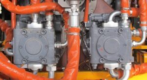
The hydraulic system of this machine comprises travelling drive, steering and suspension systems.The drive hydraulic system is a closed‑circuit system composed of variable displacement pumps and motors. The pump displacement is electronically controlled. Working parameters of the main pump or variable displacement motor can be adjusted according to actual vehicle load, so as to fully utilize engine power, improve productivity and save energy.
The steering and suspension hydraulic systems are open‑circuit systems. Each steering‑suspension bogie is driven by one steering cylinder. Hydraulic suspension is adopted, with its lifting, lowering and leveling controlled by solenoid valves.
Lifting points are designed on the flatbed vehicle to enable integral lifting of the vehicle at transport terminals and ensure safe and reliable lifting operations.